Resistance thermometers
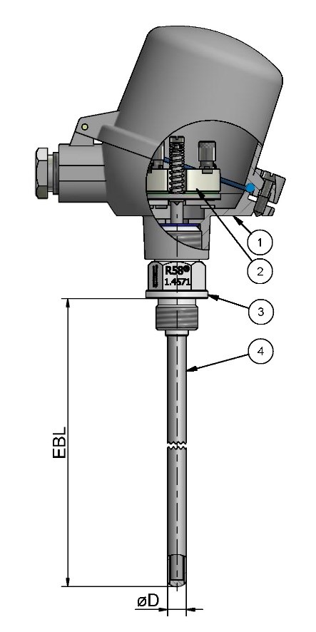
Resistance thermometers consist of a DIN 43722 protective fitting and an interchangeable DIN 43735 measuring insert which is installed in the protective fitting. The measuring insert in the protective fitting is protected against moisture, chemical and mechanical stress, among other things.
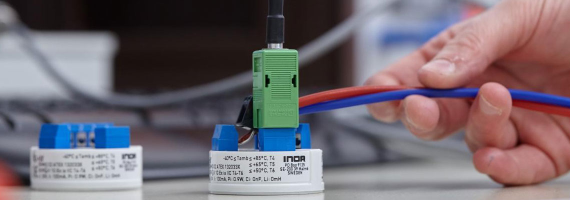
The picture illustrates an example of a resistance thermometer with a form 8(2GoH) protective fitting in accordance with DIN 43722 and a built-in measuring insert.
The measuring insert (2) of the resistance thermometer essentially consists of a flexible resistance thermometer sheathed cable similar to IEC/EN 61515 in which the measuring resistor and the inner conductors are located.
Temperature measurement using a resistance thermometer is based on the constant change in resistance of metals at alternating temperatures. Due to the high stability of the PT100 sensor in the resistance thermometer and its reproducibility, platinum (Pt) is mainly used as the resistance material today. As an alternative to PT100, nickel (Ni100) can also be used in resistance thermometers. Both metals have a positive temperature coefficient, i.e. their resistance increases with increasing temperature.
In industrial metrology today, platinum measuring resistors are predominantly used in resistance thermometers with the abbreviation "Pt100". At a temperature of 0 ºC, these measuring resistors have a nominal resistance or basic value of exactly 100 Ohm. The further basic values of the resistance thermometers for the temperature range from -200 ºC (basic value 18.52 Ohm) to +850 ºC (basic value 390.48 Ohm) can be taken in 1 ºC steps from DIN EN 60751.
In contrast to a voltage-generating thermocouple assembly, a resistor does not supply any electrical energy on its own, so that (external) energy must be supplied by an electrical measuring circuit. This is usually done with a constant current source that generates a voltage drop at the measuring resistor that is proportional to the resistance.