Thermocouple assembly
The thermocouple assembly consists of a DIN EN 50446 protective fitting, a replaceable measuring insert to DIN 43735 or a thermocouple insulated by a ceramic insulating rod.
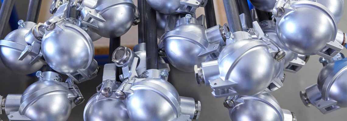
The picture shows an example of a thermocouple assembly
with a protective fitting form AKK and is constructed as follows:
• Thermocouple assembly form AKK with ceramic protection tube, a metal holding tube, a thermocouple according to IEC/EN 60584-1 and a connection head form A.
Due to the processing of highly demanding materials, the thermocouple assemblies can be used in media up to 1600°C. Thermocouples assemblies are available in the following types: K, N, R, S and B.
For glass production, we offer a special design with platinum tip, as the production of glass is highly dependent on temperature. Even slight fluctuations in the temperature structure can influence the quality of the thermocouple assembly. A type B thermocouple is preferably used for temperature measurement in a glass melt. The use of the platinum tip significantly increases the service life of the thermocouple assembly. Thermocouple assemblies with platinum tips can be used in the melt up to 1650 °C depending on the version and glass type, whereby platinum with a higher rhodium content achieves a longer service life. The thermocouple assembly can also be designed as a multiple element (usually as a 3-fold element). This makes it possible to achieve better control over the temperature distribution in the glass melt via the different immersion depths. The thermocouple assembly described below corresponds to type S or R of class 1 according to IEC/EN 60584-1, for type B of class 2.
There are a variety of technical methods for mounting temperature sensors at their place of use. Because of their design, the resistance thermometers and protective fittings shown in this list are usually screwed in, flange-mounted or welded in. The protective fittings of form 1, 2 and 3, for which, in contrast to all other protective fittings shown, the mounting type is not specified on the basis of the design, are also usually flange-mounted or screwed in at the installation location with the aid of accessories (stop flange, threaded sleeve or compression fitting).