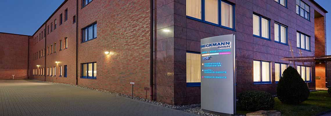
RECKMANN GMBH
Mess + Regeltechnik
Mit rund 160 Mitarbeitern entwickeln und fertigen wir in Hagen nicht nur hochwertige Temperatursensoren. Mit unserem DAkkS-akkreditierten Kalibrierlabor bieten wir Ihnen darüber hinaus eine außergewöhnliche Bandbreite an Kalibrierleistungen. So erhalten Sie bei uns Fühler und Kalibrierschein aus einer Hand.
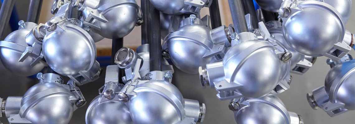
Produkte
und Zubehör
Wir produzieren Temperatursensoren wie Mantelthermoelemente, Thermoelemente und Widerstandsthermometer in Standard- sowie Sonderausführung und als explosionsgeschützte Bauformen.
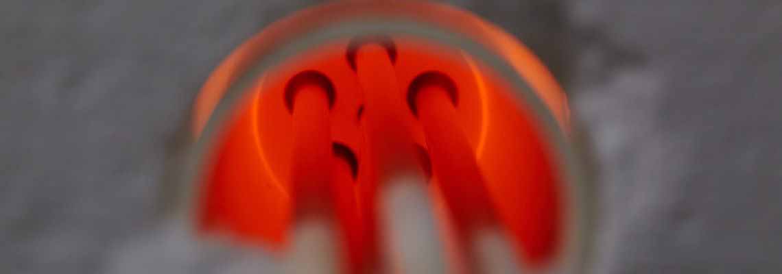
Kalibrierlabor
DIN EN ISO/IEC 17025
Wir verfügen über jahrzehntelange Erfahrung auf dem Gebiet der Temperaturmesstechnik und setzen diese zielstrebig und erfolgreich in der Kalibriertechnik für Sensoren um.
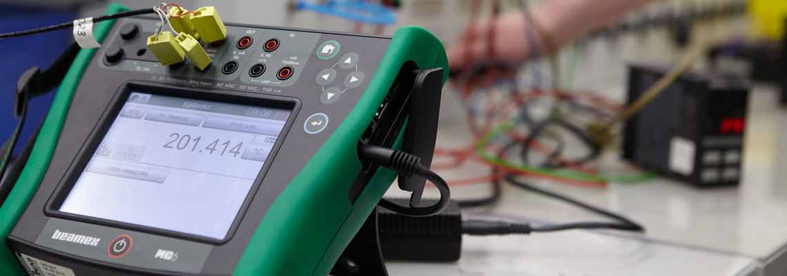
Serviceteam
Für Sie vor Ort!
Wir führen Wartung durch, justieren und kalibrieren Ihre Temperatursensorik und Industrieofenanlagen zuverlässig direkt vor Ort.
Produkte
und Zubehör
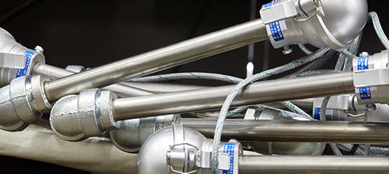
Wir produzieren Temperatursensoren wie Thermoelemente, Mantelthermoelemente und Widerstandsthermometer in Norm- sowie Sonderausführung und als explosionsgeschützte Bauformen.
Serviceteam
Für Sie vor Ort!
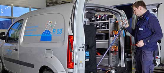
Wir warten, justieren und kalibrieren Ihre Temperatursensorik und Industrieofenanlagen zuverlässig direkt vor Ort.
Kalibrierlabor
DIN EN ISO/IEC 17025
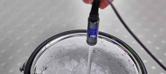
Wir verfügen über jahrzehntelange Erfahrung auf dem Gebiet der Temperaturmesstechnik und setzen diese zielstrebig und erfolgreich in der Kalibriertechnik für Sensoren um.
Reckmann Akademie
Schulungen

Wir bieten Ihnen die Möglichkeit, unsere Seminare wochentags in unserem Hause, aber auch als Inhouse-Schulung bei Ihnen durchzuführen.
Downloads
Infomaterial
- Ex-Temperatursensoren
- Große Thermoelemente R7
- Kleine Thermoelemete R8
- Mantelthermoelemente R9